Application · Excavations and retaining walls
Supported excavations, built in the model the way they are built on site.
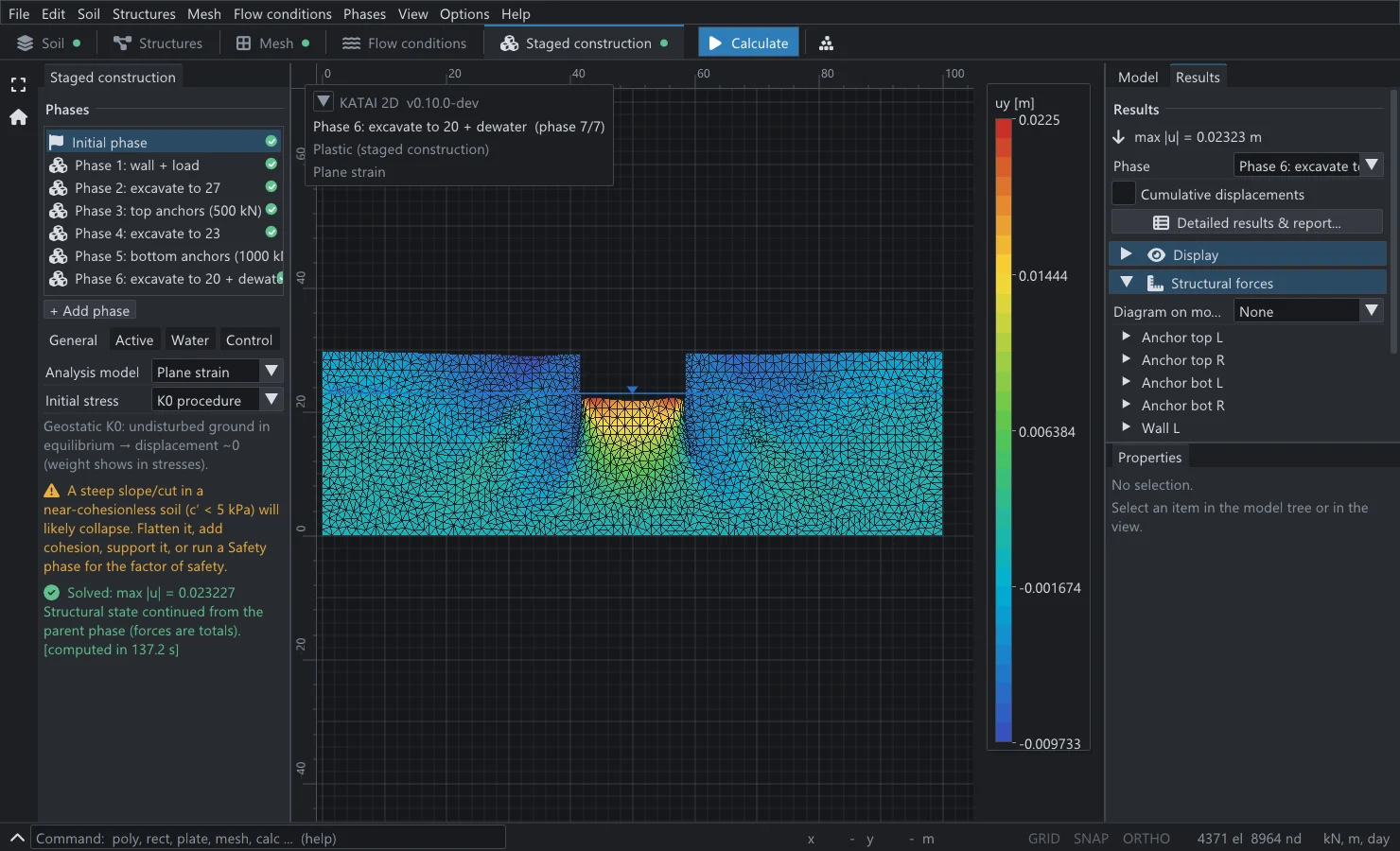
A retaining wall is not designed for one load case; it is designed for a sequence. KATAI 2D models that sequence — install the wall, excavate a level, stress the anchors, lower the water, excavate again — carrying stresses, pore pressures and structural forces from each stage into the next, and returning bending moment, shear and axial force at every station of every member.
The engineering problem
The bending moment in an embedded wall depends on the order in which the ground was removed and the supports were installed. An anchor stressed before the next dig carries a different force from one installed after it; a wall that has already rotated at the first stage arrives at the last one with a different shape. An analysis that applies the final geometry in one step solves a different problem from the one on the drawings.
The second difficulty is the contact. Soil slips against a wall face, and the amount of friction it can mobilise there governs the earth pressure. A model that glues the soil to the wall overestimates the support the soil gives; one that removes the friction entirely underestimates it. A zero-thickness interface with its own Coulomb strength is the standard resolution, and it has to be on both faces.
The formulation
The full statement of what is solved, element by element and model by model, is on the theory and constitutive models pages.
What KATAI 2D does
- Plates for walls, linings and slabs, with axial and bending stiffness per metre and optional elastoplastic limits Mp and Np — a wall can form a plastic hinge.
- Node-to-node anchors and struts with out-of-plane spacing, a prestress (lock-off) force, and separate tension and compression limits.
- Geogrids as tension-only sheets with a tension cap; embedded beam rows for pile rows with shaft and base resistance.
- Zero-thickness interfaces on one or both faces of a wall, taking their strength from the adjacent soil through Rinter.
- Inherited activation. A phase lists only what changes: regions deactivated, members activated, a new water level. Everything else carries forward.
- Per-phase water. Each phase can carry its own phreatic level, wells and drains, so dewatering before a dig is a phase, not a workaround.
- Force diagrams. N, Q and M at stations along every member, the envelope over the phases, and whether the member yielded.
Verified
The numbers, with their sources.
Each row is a case in the generated verification matrix, asserted by an automated test on every build of release 0.9.0.
| Benchmark | Reference | KATAI 2D | Case |
|---|---|---|---|
| Two beams in bending, deflection and peak moment from one run | beam theory; published 50 kNm | deflection −0.000% · moments +0.00% / +1.04% | KV-STR-003 |
| Prestressed anchor on a stiff block — force after lock-off at 500 kN | equivalent point-load model (independent path) | 499.919 kN · 0.016% | KV-STR-001 |
| Block sliding on an interface — horizontal failure force | Coulomb joint closed form | −0.59%, converging −1.31 / −0.59 / −0.27% with refinement | KV-STR-002 |
| Staged excavation — pit-floor heave after removing a layer | 1D elastic unloading closed form | +0.0% | KV-EXC-001 |
| Partial stage: ΣMstage = 1, 0.5, 0.25 on a linear soil | linear superposition | proportional to 10−12 | KV-EXC-002 |
| Lowering the water table in a phase — settlement | Terzaghi effective stress, closed form | +0.01% | KV-CST-003 |
| Geogrid in tension, and the cap it stops at | plane-strain closed form | 2.000000 kN/m · +0.000% | KV-STR-005 |
| Plate, anchor and geogrid at the end of a consolidation phase | the same model as a drained phase | moment 21.621032 = 21.621032 kNm/m | KV-STR-006 |
Each structural element is verified on a problem small enough to have an exact answer, then the same element is used in the full model. The last row matters for long excavations in clay: a wall that stays in the ground while the ground consolidates must arrive at the drained answer once the excess pore pressure is gone, and it does, to eight figures.
The complete record, with every tolerance band, is on the verification page.
In Python
The analysis as a script.
import katai

prj = katai.Project("Anchored excavation", mesh_size=2.0, auto_refine=False)

sand = prj.materials.mohr_coulomb("Berlin sand", E=3.0e4, nu=0.3,
                                  c=5.0, phi=32.0, gamma=19.0)

# Ground, split so the pit can be dug out of it later.
prj.geometry.rectangle(0, 0, 30, 12, material=sand, name="Below formation")
pit = prj.geometry.rectangle(0, 12, 12, 20, material=sand, name="Pit")
prj.geometry.rectangle(12, 12, 30, 20, material=sand, name="Retained ground")

# A diaphragm wall with an interface on each face, and a prestressed anchor.
wall = prj.structures.plate((12, 20), (12, 6), EA=1.2e7, EI=1.0e5, w=5.0,
                            interfaces="both", name="Diaphragm wall")
anchor = prj.structures.anchor((12, 18), (20, 14), EA=2.0e5, spacing=2.5,
                               prestress=300.0, name="Anchor row 1")

prj.initial(procedure="k0", exclude=[anchor])
prj.phases.plastic("Excavate to formation", activate=[anchor], deactivate=[pit])

job = prj.run()
print(katai.summary(job, prj))
# wall: |M|max = 58.3 kNm/m, |N|max = 325.7 kN/m; anchor N = 195.4 kN/m
# largest movement anywhere: 43.3 mm, at (3, 12) -- the pit floor
The printed values are the output of the published 0.9.0 wheel. katai.summary() gives every extreme together with the place it occurs.
The whole scripting surface is documented on the Python API page.
Stated limits
What this analysis does not do, in the same place as what it does. A limit you know about is an engineering judgement; one you find out about later is an error.
- Plane strain: anchors and pile rows are discrete members smeared over their out-of-plane spacing, and corner effects of a real pit are outside the model.
- Reactions at a support that a structural element ends on exclude the element’s own end force; the run says so (K2D-A004) and the force is read from the element’s diagram.
- Interfaces placed along a line that is not on mesh edges are bonded, with a warning (K2D-G009), rather than silently dropped.
Questions
Can KATAI 2D model a multi-level anchored or strutted excavation?
Yes. Each excavation level, each anchor row and each change of water level is a phase; activation is inherited, so a phase states only what changes. Anchors carry a prestress force and are activated in the phase in which they are stressed.
How are anchors with out-of-plane spacing handled in a 2D model?
Anchors and pile rows are discrete members, so they carry their spacing in metres and the engine divides their stiffness and capacity by it. Plates and geogrids are continuous and are entered per metre out of plane.
Does the wall yield?
If you give it a plastic moment Mp or a plastic axial force Np, yes: the plate becomes elastoplastic and the result reports whether it yielded. A value of zero means unlimited, not zero capacity.
Related
Other analyses on the same engine.
Foundations & bearing capacity
Strip, circular and piled foundations — settlement, load–displacement, limit load.
Prandtl N_c: +0.6% Read more → ApplicationGroundwater flow & seepage
Confined and free-surface flow, wells, drains and barriers — coupled to the soil.
dam discharge +1.02% Read more → ApplicationSlope stability
Factor of safety by φ–c reduction; the failure mechanism is found, not assumed.
FoS 1.384 vs 1.380 charted Read more →Install it, run a published benchmark, check the number.
KATAI 2D is free under Apache‑2.0, installs in one line and ships the input files of the benchmarks it is verified against. The fastest way to judge it is to rerun one.